More details on the ALICE TRD
The Transition Radiation Detector (TRD) is the main electron detector in ALICE. In conjunction with the TPC and the ITS, it provides the necessary electron identification capability to study:
- Production of light and heavy vector mesons as well as the continuum in the di-electron channel
- Semi-leptonic decays of hadrons with open charm and open beauty via the single-electron channel using the displaced vertex information provided by the ITS
- Correlated DD and BB pairs via coincidences of electrons in the central barrel and muons in the forward muon arm
- Jets with high Et by requiring several high pr tracks in one single TRD module.
Technical Details
Principle of Operation
An individual detector module consists of a radiator and a drift chamber operated with Xe/CO2 mixture (85%/15%). The drift electrode is glued directly to the radiator. The particles pass through the radiator, where electrons emit transition radiation (TR) and then enter the conversion and drift region of the readout chamber.
The conversion and drift region is 30 mm deep. The drift field of 700 V/cm corresponds to a drift velocity of 1.5 cm/μs. The secondary electrons are amplified in the multi-wire proportional counter with a gas gain of around 3500. The wires run in φ-direction where the best position resolution has to be achieved for an accurate momentum determination. The readout pads are rectangular with an average size of 0.7 cm x 8.7 cm. The induced signal on the pads is read out every 100 ns to record the time evolution of the signal. The ratios of charges recorded on adjacent pads for each time sample allow position determination along the track segments in one chamber, called tracklet. From the inclination of the tracklet one can infer the momentum.
The Radiator
The radiator is optimized to provide the best compromise between transition radiation yield, radiation thickness and mechanical stability. The final radiator consists of polypropylene fibre mats of 3.2 cm total thickness, sandwiched between two Rohacell foam sheets of 0.8 cm thickness each. The foam is reinforced by carbon fibre sheets with a thickness of 0.1 mm laminated onto the outer surface.
TRD radiator design
Scanning electron microscope images of the used radiator materials. Rohacell on the left and polypropylene fibre mats on the right.
Electronics Overview
The front readout electronics consists of: an analog ASIC containing 18 channels of the Pre-Amplifier Shaper (PASA) and output buffers; a mixed analog/digital ASIC containing 18 channels of ADCs, Tracklet PreProcessor (TPP) and Event Buffers and 4 CPU's process 4 tracklets in parallel for all channels. Both ASICs, assembled in a Multi-Chip Module (MCM), are mounted directly on the readout chambers. The GTU serves the TRD stack with 6 readout chambers in order to provide trigger information on high pt tracks.
The components from ADC to Tracklet processor in the figure are contained in a single one mixed analog/digital chip called TRAP.
Data Processing
During the drift time, the analog to digital transformation and data processing in the Tracklet PreProcessor (TPP) are performed. The tracklets are shipped via optical links to the Global Tracking Unit (GTU) the 6 individual readout chambers in a stack. The GTU combines and processes the trigger information from individual readout chambers and sends a L1 trigger signal to the central trigger processor as well as all TRD raw data to the Data Acquisition (DAQ) for triggered events.
Performance
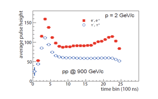
Transition Radiation Signature
The figure shows the average pulse height summed over adjacent pads recorded as a function of time for pions and electrons. For electrons there is a significant increase in the average pulse height at later times, due to the preferential absorption of transition radiation near the entrance of the drift chamber.
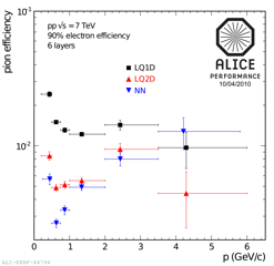
Pion Efficiency
The performance of the particle identification is expressed in terms of the pion efficiency, which is the fraction of pions wrongly identified as electrons. We employ the following methods: (i) one-dimensional likelihood on the total integrated charge (LQ1D) (ii) bidimensional likelyhood on charge as a function of drifttime (LQ2D); and (iii) a neural network (NN). The momentum dependence of the pion efficiency is shown on the right. While the LQ1D is the simplest and, consequently, more robust method, the full exploitation of the TRD capability is reached taking advantage of the temporal pattern of the signal, utilized in the LQ2D and NN methods. The present pion suppression factor of 100 or greater obtained from collision data confirm indeed the design value found in testbeams with prototypes.
J/ψ Measurement
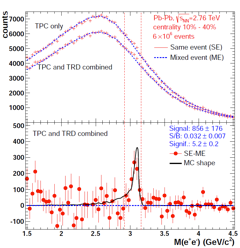
The figure shows the effect of the TRD electron identification for the J/ψ measurement in the 10-40% most central Pb-Pb collisions. The TRD electron identification is based on the total integrated charge, requiring an electron efficiency of 90% and tracks reconstructed with signals in at least 4 layers. For the data shown here, collected in 2010, 7 out of the 18 TRD supermodules were installed, implying a large acceptance reduction for quarkonium measurements. Thus the TRD particle identification was used whenever available. Despite reduced coverage, due to its good discrimination power, the TRD contributes to a reduction of the combinatorial background. Compared with a TPC only analysis the significance improves by about 20%.
Trigger: Transverse Momentum Resolution
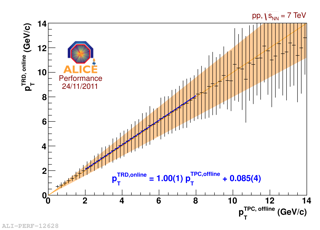
The correlation of on-line and off-line transverse momenta is shown for on-line tracks matched to a TPC track. Each data point is the mean of the distribution and the error bars show the standard deviation (misalignment is not corrected).
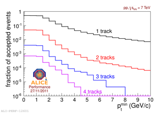
Trigger: Rejection Power
The trigger selectivity is also quantified by the fraction of events passing the criterion of a number of tracks, each with a minimal pt value. The different lines correspond to different minimum number of tracks in a TRD stack whereas the abscissa shows the required pt . Requiring 3 tracks above 3 GeV/c is any TRD stack was found to be a suitable condition to trigger on jets. This threshold results in a good rejection of about 104 .